
What Is I2C Protocol? Working Principles and Applications in TFT LCD Touch Modules
 2026-11-10
 10:30


Introduction
When integrating a TFT LCD with a capacitive touchscreen, engineers need to understand the difference between display data transmission and touch communication. Although both functions may be part of the same display assembly, they often use separate interfaces.
I2C (Inter-Integrated Circuit) is widely used to connect a host processor with peripheral devices, including capacitive touch controllers, sensors, EEPROMs and other control components. In many TFT LCD systems, I2C handles touch data and peripheral communication, while interfaces such as RGB, LVDS or MIPI DSI transmit image data to the display panel. In TFT LCD modules with capacitive touch panels (CTP), I2C typically enables communication between the host processor and the touch controller rather than carrying display image data.
Understanding how the I2C protocol works is therefore important when selecting a display module, checking host-interface compatibility and planning hardware integration.
This guide explains how I2C communication works, its electrical characteristics, key design considerations and practical applications in TFT LCD touch display integration.
What Is the I2C Protocol?
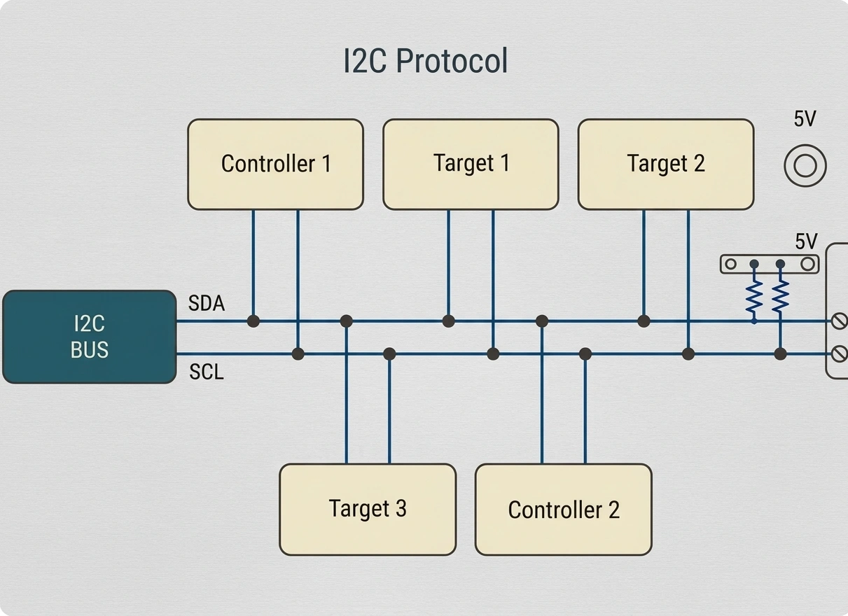
I2C, short for Inter-Integrated Circuit, is a synchronous, bidirectional, serial communication protocol originally developed by Philips Semiconductors (now NXP Semiconductors).
It enables a host controller to communicate with multiple peripheral devices over a shared two-wire bus.
The two primary signal lines are:
- SDA (Serial Data Line):Transfers data between connected devices.
- SCL (Serial Clock Line):Provides the clock signal that synchronizes communication.
Both lines are typically open-drain or open-collector and require pull-up resistors to establish a HIGH logic level.
Unlike point-to-point communication interfaces, I2C supports multiple addressed devices on the same bus. Each device responds to its assigned address, allowing the host controller to communicate with individual peripherals without requiring a separate data connection for every component.
Key Characteristics of I2C
|
Parameter |
Description |
|
Communication type |
Synchronous serial |
|
Signal lines |
SDA and SCL |
|
Data direction |
Bidirectional |
|
Device addressing |
7-bit or 10-bit |
|
Bus architecture |
Shared multi-device bus |
|
Electrical configuration |
Open-drain / open-collector |
|
Typical applications |
Sensors, EEPROMs, RTCs, touch controllers |
|
Common I/O voltage levels |
1.8V and 3.3V, depending on device specifications |
One of the main advantages of I2C is its relatively low pin count. Multiple peripheral devices can communicate with a microcontroller through the same SDA and SCL connections, reducing routing complexity compared with interfaces that require dedicated communication lines for each peripheral.
How Does I2C Communication Work?
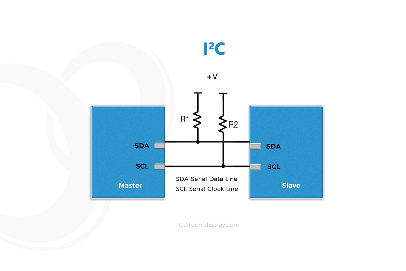
I2C communication uses a controller-generated clock to coordinate data transfer between the controller and target devices. Each transaction begins when the controller addresses the intended target.
SDA and SCL: The Two Essential Signals
The I2C bus operates through two primary signal lines.
SDA – Serial Data Line
SDA carries the actual data exchanged between the controller and target device. It is bidirectional, meaning both devices can transmit data at different stages of a communication transaction.
SCL – Serial Clock Line
SCL provides the timing reference for data transmission. In conventional I2C operation, the controller generates the clock signal, although a target device may use clock stretching to delay communication when supported.
Both signal lines are shared across the connected devices.
During data transfer, SDA generally remains stable while SCL is HIGH and changes when SCL is LOW. The receiving device reads the data while SCL is HIGH. The main exceptions are the START and STOP conditions, which are indicated by specific SDA transitions while SCL is HIGH.
I2C Controller and Target Devices
An I2C system typically consists of a controller and one or more target devices.
- Controller:Initiates transactions, generates the clock and sends target addresses.
- Target:Responds when its address is selected and performs the requested read or write operation.
Older technical documents often use the terms Master and Slave. Controller and Target are the more recent terminology.
For example, an embedded display system may contain:
- An MCU or MPU acting as the I2C controller.
- A capacitive touch controller acting as an I2C target.
- Additional peripheral devices, such as sensors or an EEPROM, connected to the same bus.
This arrangement allows the host processor to retrieve touch information and configure peripheral devices without dedicating separate communication interfaces to each one.
Some I2C systems also support multiple controllers, with bus arbitration used to manage access when more than one controller attempts to initiate communication.
I2C Addressing: 7-Bit and 10-Bit Addresses
I2C uses device addressing to identify the target involved in a communication transaction.
The two commonly defined addressing formats are:
- 7-bit addressing:Supports up to 128 possible address values, although some are reserved for special purposes.
- 10-bit addressing:Provides a larger address space for systems requiring more device addresses.
In capacitive touch-controller applications, 7-bit addressing is commonly used, while 10-bit addressing is less common. Engineers should confirm the address format and value specified in the touch-controller datasheet.
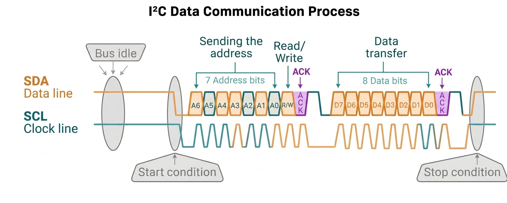
In a standard 7-bit transaction, the controller sends the target address followed by a read/write bit.
The read/write bit indicates the direction of the subsequent data transfer:
- 0: Write operation.
- 1: Read operation.
A common source of confusion is the difference between a 7-bit device address and an 8-bit address byte shown in some device datasheets. The latter may include the read/write bit as its least significant bit.
When configuring an I2C peripheral, engineers should verify the address format specified by the device manufacturer rather than copying an address value without checking how it is represented.
START, STOP, ACK and NACK Conditions
An I2C transaction follows a defined sequence of signaling conditions.
START Condition
A START condition occurs when SDA transitions from HIGH to LOW while SCL remains HIGH. It indicates the beginning of a communication transaction.
Address Transmission
The controller sends the target device address and the read/write bit.
ACK or NACK
After receiving a byte, the receiving device indicates whether it has acknowledged the transfer.
- ACK (Acknowledge): The receiver pulls SDA LOW during the acknowledgment clock pulse.
- NACK (Not Acknowledge): SDA remains HIGH during the acknowledgment clock pulse.
A NACK does not always indicate a hardware failure. For example, a target may not respond to an unsupported address, or a controller may intentionally terminate a read operation by sending NACK after the final byte.
Data Transfer
Data is transferred in 8-bit units, with an acknowledgment bit following each byte.
STOP Condition
A STOP condition occurs when SDA transitions from LOW to HIGH while SCL remains HIGH, marking the end of the transaction.
For operations that require multiple stages without releasing the bus, a repeated START condition can be used instead of a STOP followed by a new START.
I2C Communication Speed Modes
I2C supports several operating modes with different maximum clock frequencies.
|
I2C Mode |
Maximum Clock Frequency |
Typical Use |
|
Standard-mode |
100 kHz |
Basic peripheral communication |
|
Fast-mode |
400 kHz |
Common embedded applications |
|
Fast-mode Plus |
1 MHz |
Higher-speed peripheral communication |
|
High-speed Mode |
3.4 MHz |
Specialized high-speed applications |
The I2C specification also defines Ultra Fast-mode (UFm) at up to 5 Mbit/s. Unlike conventional I2C modes, UFm uses unidirectional data transmission without the standard acknowledgment mechanism. It is therefore not a higher-speed bidirectional I2C mode and is rarely used in conventional TFT LCD or capacitive touch-controller applications.
These frequencies represent protocol-defined maximum rates, not guaranteed operating speeds for every device. The actual clock frequency must be supported by the controller and all connected target devices.
In TFT LCD touch applications, Standard-mode or Fast-mode is often sufficient. The appropriate setting depends on the touch-controller specifications, bus capacitance, wiring and signal integrity.
Increasing the I2C clock frequency does not necessarily improve system performance. If connected devices cannot support the selected mode or the bus cannot maintain adequate signal integrity, communication errors may occur.
Key Electrical Design Considerations for I2C
Understanding the communication protocol is only part of a successful I2C implementation. Electrical compatibility and PCB design also determine whether the bus operates reliably.
Pull-Up Resistors for SDA and SCL
One of the most important electrical characteristics of I2C is its open-drain signaling structure.
I2C devices generally pull the signal lines LOW when transmitting a logical zero. To generate a logical HIGH, the device releases the line, allowing the external pull-up resistor to raise the signal voltage.
Therefore, pull-up resistors are required on both SDA and SCL.
Their values influence:
- Signal rise time.
- Power consumption.
- Maximum supported communication frequency.
- Overall bus reliability.
If the pull-up resistance is too high, the signal may rise too slowly to meet the timing requirements. If it is too low, devices may need to sink excessive current when pulling the line LOW.
The pull-up resistance should be selected based on the bus timing requirements and the electrical limits of the connected devices.
A useful approximation for the maximum pull-up resistance is:
Rp(max) = tr / (0.8473 × Cbus)
Use consistent SI units: rise time in seconds and bus capacitance in farads, with the resulting resistance expressed in ohms.
Where:
- Rp(max) = Maximum pull-up resistance.
- tr = Maximum permitted signal rise time.
- Cbus = Total bus capacitance.
The minimum pull-up resistance should also be checked against the maximum permitted LOW-level output voltage and the device’s sink-current capability. A simplified calculation is:
Rp(min) = (VPU – VOL(max)) / IOL
Where:
- Rp(min) = Minimum pull-up resistance.
- VPU = Pull-up supply voltage.
- VOL(max) = Maximum permitted LOW-level output voltage.
- IOL = Guaranteed LOW-level sink current at VOL(max).
The selected pull-up resistance should fall within the range allowed by both calculations.
When multiple devices or modules share an I2C bus, their onboard pull-up resistors may be connected in parallel, reducing the effective resistance and increasing the current drawn when the bus is LOW.
Before adding external pull-ups, check whether the host board or display module already includes them and calculate the combined resistance.
I2C Voltage Compatibility
I2C devices may operate at different logic supply voltages, including 1.8V and 3.3V.
However, sharing the same two signal lines does not automatically make devices with different logic voltages electrically compatible.
Before connecting an MCU to a touch controller, engineers should verify:
- The I/O supply voltage of each device.
- The permitted input HIGH and LOW voltage thresholds.
- Whether the SDA and SCL pins are open-drain.
- The voltage connected to the bus pull-up resistors.
- Whether a bidirectional level shifter is required.
Because I2C uses open-drain signaling, the pull-up voltage determines the HIGH-level bus voltage. Open-drain signaling alone does not guarantee voltage compatibility between devices operating at different logic levels. If the selected pull-up voltage exceeds the permitted input voltage of a connected device, the bus voltage must be adjusted or a suitable bidirectional I2C level shifter must be used.
For example, a 1.8V touch controller connected to a 3.3V host may require a suitable bidirectional level-shifting circuit if its I/O pins are not 3.3V tolerant.
Bus Capacitance and Signal Integrity
I2C is generally designed for relatively short-distance communication within electronic systems.
The total bus capacitance on each signal line includes contributions from:
- PCB traces.
- FPC or cable connections.
- Connector contacts.
- Device input pins.
- Additional components connected to the bus.
As bus capacitance increases, SDA and SCL transitions become slower. This can affect signal rise time and limit the maximum reliable communication frequency.
Under the I2C specification, the maximum capacitive load is 400 pF per bus line for Standard-mode and Fast-mode, while Fast-mode Plus allows up to 550 pF. Other operating modes have different electrical limits, so engineers should refer to the applicable specification and device datasheets.
If bus capacitance exceeds the applicable limit, possible design approaches include shortening connections, optimizing pull-up resistor values within the permitted electrical range, or using a compatible I2C bus buffer or extender.
For display assemblies, the connection between the host board and touch controller should be evaluated as part of the complete electrical design.
Longer connections, additional connectors and poor PCB routing can increase parasitic capacitance or introduce noise. Good design practices include keeping I2C traces reasonably short, maintaining a suitable ground reference, avoiding unnecessary stubs and verifying signal quality on the actual hardware.
Wiring and PCB Layout Considerations
Although I2C requires only two communication signals, the complete electrical connection must also provide power and a common ground reference.
For a typical I2C-connected touch controller, the relevant connections may include:
- SDA
- SCL
- VDD
- GND
- INT (interrupt)
- RESET
INT and RESET are not part of the two-wire I2C bus itself, but are commonly provided as additional signals in touch-controller integration.
Their functions and electrical requirements depend on the controller and module design.
For reliable integration, engineers should verify the connector pin assignment, signal voltage, timing requirements and reset sequence against the module specification and controller datasheet.
How Is I2C Used in TFT LCD Touch Modules?
I2C has an important role in embedded display systems, particularly when a TFT LCD is integrated with a projected capacitive (PCAP) touchscreen.
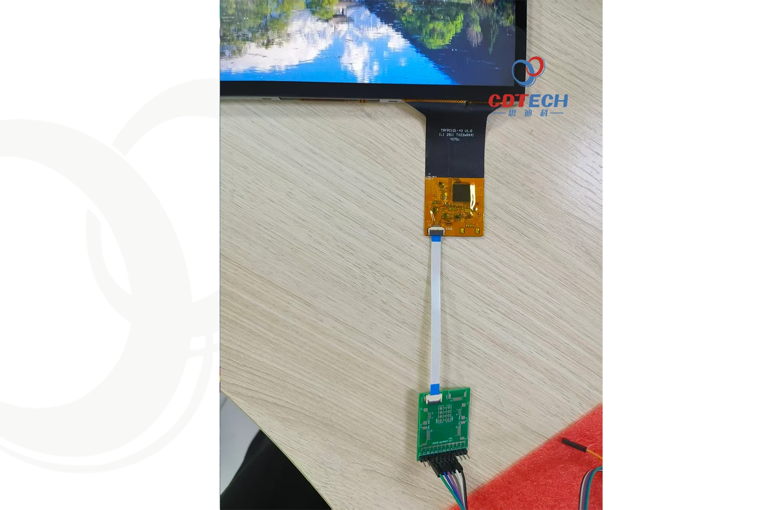
CDTech 10.1-inch IPS TFT LCD module with In-Cell Touch, featuring LVDS display and IIC touch interfaces.
However, it is essential to distinguish between touch communication and display image transmission.
I2C Communication with Touch Controllers
In a PCAP touchscreen assembly, the touch sensor detects changes in capacitance when a finger or conductive object approaches the sensing surface.
The touch controller processes these sensor signals and determines touch information, such as:
- Touch coordinates.
- Number of detected touch points.
- Touch status.
- Contact or release events.
The host processor reads the processed touch information through the communication interface supported by the touch controller, commonly I2C.
A simplified communication structure is:
Host MCU / MPU ↔ I2C (SDA / SCL) ↔ Touch Controller ↔ PCAP Sensor
The host processor uses the reported touch coordinates and status to update the application’s user interface.
For example, in an industrial HMI, a touch controller may report the coordinates of an operator’s input. The host processor then interprets the coordinates and triggers the corresponding control function.
I2C vs. Other Display Interfaces
I2C serves a different purpose from the interfaces commonly used to transmit image data to TFT LCD panels. In many embedded display systems, RGB, LVDS and MIPI DSI carry pixel data, while I2C is commonly used for control and peripheral communication.
|
Interface |
Primary Function |
Typical Application |
|
I2C |
Low-speed control and peripheral communication |
Touch controllers, configuration registers and sensors |
|
SPI |
Serial data transfer and device control |
Small displays, display controllers and peripheral devices |
|
RGB |
Parallel pixel data transmission |
TFT LCD modules requiring direct pixel data input |
|
LVDS |
High-speed differential pixel data transmission |
Medium- and large-size TFT LCD modules |
|
MIPI DSI |
High-speed display data transmission |
Compact embedded displays and mobile-oriented systems |
The interface combination depends on the display controller, touch controller and host processor. A TFT LCD module may use one interface for image data and another for touch or configuration signals.
I2C Communication in a TFT LCD Module
In a typical TFT LCD system with a capacitive touch panel, image transmission and touch communication operate through separate signal paths.
For example, a host processor may communicate with the LCD panel through an LVDS interface while using I2C to communicate with the capacitive touch controller.
A practical example is the CDTech 10.1-inch IPS TFT LCD module with In-Cell Touch. It uses LVDS for display image transmission and IIC (I2C) for touch communication, illustrating how the two interfaces work together within an integrated display module.
The specific interface configuration depends on the display module and touch-controller design.
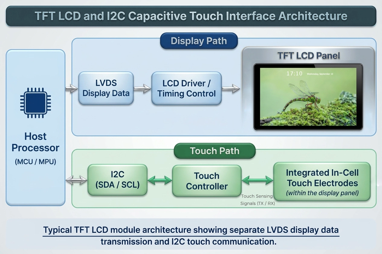
Conceptual architecture. Actual touch-controller and sensor implementation may vary by module.
What Should Engineers Check When Selecting an I2C Touch Display?
When integrating a TFT LCD with an I2C-based touchscreen, engineers should evaluate more than the presence of SDA and SCL pins.
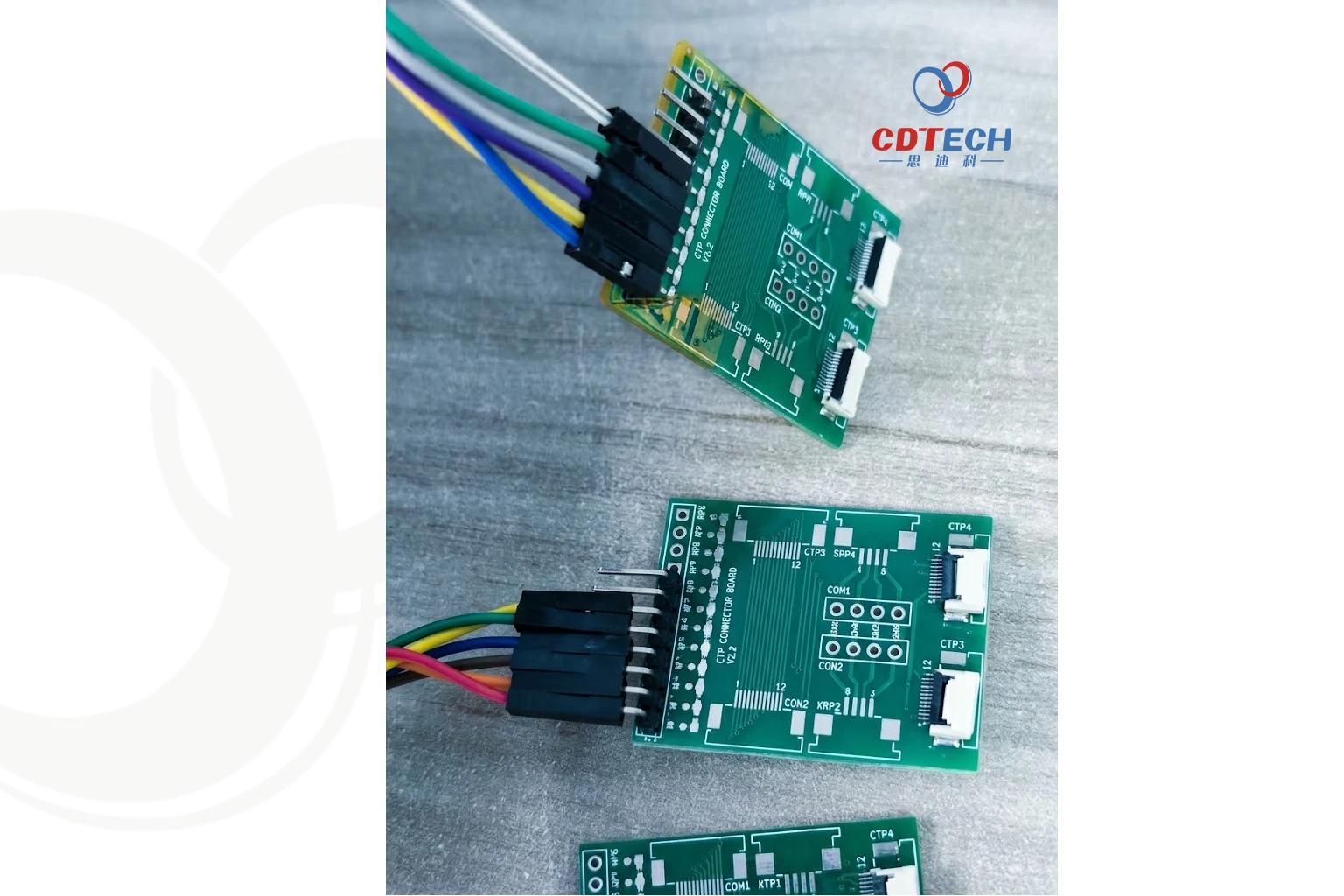
CDTech CTP connector board testing setup, connecting the host to the capacitive touch controller via SDA, SCL, and power lines.
Important selection considerations include:
- Controller compatibility: Confirm that the host processor supports the required I2C mode and can communicate with the selected touch controller.
- I/O voltage: Verify that the host and touch controller use compatible logic levels or provide appropriate level shifting.
- Device address: Check the I2C address and ensure it does not conflict with other devices sharing the same bus.
- Pull-up resistors and bus capacitance: Verify the pull-up configuration and total bus capacitance to ensure reliable signal transitions at the selected clock frequency.
- Interrupt and reset signals:Confirm whether additional INT and RESET connections are required and how they should be configured.
- Connector and pin assignment: Verify the FPC pinout, cable orientation and electrical connections.
- Driver support: Ensure that the operating system or firmware supports the touch controller’s driver and initialization sequence. Interface options vary by module design. For a broader comparison, see our guide to USB, I2C, and SPI selection for SMT touch panels
- Environmental requirements: For industrial and automotive applications, evaluate operating temperature, immunity to electrical noise, ESD protection and mechanical integration.
A display module may have the correct physical size and resolution but still require additional host-side hardware or software work if the touch interface is not compatible with the target platform.
I2C vs. SPI: Which Interface Should You Choose?
I2C and SPI are both widely used serial communication interfaces in embedded systems. However, they differ in their electrical structure, wiring requirements and performance characteristics.
|
Comparison |
I2C |
SPI |
|
Signal lines |
SDA, SCL |
Typically MOSI, MISO, SCLK and CS |
|
Communication |
Synchronous, bidirectional |
Synchronous, typically full-duplex |
|
Device selection |
Device addressing |
Chip-select signal |
|
Multiple devices |
Shared bus with addressing |
Shared signals with separate CS lines in common configurations |
|
Typical speed |
Up to 3.4 MHz in conventional bidirectional High-speed Mode |
Often higher, depending on device specifications |
|
Hardware complexity |
Relatively low pin count |
More signal connections |
|
Common applications |
Sensors, touch controllers, configuration |
Displays, memory and high-speed peripherals |
When Is I2C a Better Choice?
I2C is suitable when:
- Multiple low- to moderate-speed peripherals share a communication bus.
- PCB pin count and wiring complexity need to be minimized.
- Device addressing is useful.
- The communication involves configuration data, sensor readings or touch information.
When Is SPI a Better Choice?
SPI may be more appropriate when:
- Higher communication throughput is required.
- The peripheral needs faster data transfer.
- The host has sufficient GPIO resources.
- Dedicated chip-select signals are acceptable.
Neither interface is universally better.
The decision should be based on the peripheral’s supported interfaces, data transfer requirements, system architecture and available hardware resources.
For TFT LCD applications, it is particularly important to distinguish SPI-based display modules from I2C-based touch-controller connections. The two interfaces may serve entirely different functions within the same embedded product.
For a more detailed comparison of display interface selection, see our guide to choosing between SPI and I2C for LCD modules when pin count is limited.
Common I2C Communication Problems and Troubleshooting
I2C is relatively simple to implement, but electrical mismatches, incorrect configuration and signal integrity problems can cause communication failures.
The following table outlines common symptoms and practical diagnostic directions.
|
Problem |
Possible Causes |
Recommended Checks |
|
I2C device not detected |
Incorrect address, wiring or power supply |
Verify the device address, SDA/SCL connections and supply voltage |
|
No ACK response |
Incorrect addressing, device not initialized or electrical fault |
Check the address format, startup sequence and communication waveform |
|
Unstable communication |
Poor signal integrity, incorrect pull-ups or timing mismatch |
Inspect SDA/SCL waveforms, rise time and bus capacitance |
|
SDA or SCL stuck LOW |
Device holding the bus, short circuit or incomplete transaction |
Check bus voltage and inspect device reset and recovery behavior |
|
Touchscreen not responding |
Incorrect controller configuration, missing interrupt or driver issue |
Verify INT, RESET, I2C communication and firmware configuration |
Address Detection and ACK Failures
For an undetected I2C target or missing ACK response, first verify the device address, power supply, SDA/SCL connections and initialization status. Check whether the host uses the correct 7-bit or 8-bit address format.
If the basic checks are correct, use a logic analyzer or oscilloscope to inspect the START condition, transmitted address and ACK bit during the ninth clock pulse. An I2C address scanner may also help, although some devices do not support generic probing.
Unstable Communication
Intermittent communication failures may be related to excessive bus capacitance, unsuitable pull-up resistance or signal interference.
Engineers should inspect the actual SDA and SCL waveforms rather than assuming that the configured I2C clock frequency is the only issue.
Check signal rise time, LOW-level voltage, clock timing and the overall electrical loading of the bus.
SDA or SCL Stuck LOW
A bus stuck LOW can prevent new transactions from starting.
Possible causes include a peripheral holding the line LOW, an interrupted transaction or an electrical short.
For devices that support bus recovery, a common approach is to send clock pulses followed by a STOP condition. However, not all I2C target devices support this procedure. Some touch controllers may require a hardware RESET signal or a controlled power cycle to restore normal operation. Always follow the recovery instructions in the device datasheet.
For display integration, it is also important to check whether the touch controller has completed its startup sequence before the host begins communication.
When Should Engineers Use I2C?
I2C is a practical choice for embedded systems that require communication between a host processor and multiple peripheral devices without using a large number of dedicated signal lines.
Typical applications include:
- Industrial HMIs:Communication with touch controllers, sensors and configuration devices.
- Medical equipment:Peripheral communication in monitoring and control systems, subject to the device’s electrical and regulatory requirements.
- Automotive electronics:Communication with supported peripheral controllers and monitoring components.
- Smart home appliances:Touch input, environmental sensing and peripheral configuration.
- Embedded control systems:Connecting microcontrollers to EEPROMs, real-time clocks and other low-speed devices.
However, I2C is not intended to replace every communication interface.
Its relatively limited bandwidth, electrical bus loading and distance constraints make it unsuitable for applications requiring high-speed image transmission or long-distance data communication.
For display systems, the most appropriate solution is often a combination of interfaces: a dedicated display data interface for image transmission and I2C for touch-controller communication or peripheral control.
The final selection should be based on the complete system architecture rather than the interface name alone.
Frequently Asked Questions About I2C
Q: What is the I2C protocol used for?
A: I2C is used for communication between integrated circuits in embedded electronic systems. Typical applications include connecting microcontrollers to sensors, EEPROMs, real-time clocks, GPIO expanders and capacitive touch controllers.
Q: What are SDA and SCL in I2C?
A: SDA is the Serial Data Line, which carries bidirectional communication data between the controller and target devices. SCL is the Serial Clock Line, which provides timing synchronization and is typically generated by the controller. Both lines generally use open-drain or open-collector signaling with pull-up resistors. Some target devices also support clock stretching by holding SCL LOW.
Q: Is I2C faster than SPI?
A: Generally, SPI can support higher data transfer rates than I2C, although actual performance depends on the specific devices and system design. I2C is often preferred for lower-speed peripheral communication because it uses fewer signal lines and supports device addressing.
Q: Can an LCD display use I2C?
A: Yes. Some character LCDs, small display modules and display controllers support I2C for control or data communication. However, many TFT LCD panels use RGB, LVDS, MIPI DSI or other dedicated interfaces for image data transmission.
Q: Does a TFT LCD touchscreen use I2C?
A: Many TFT LCD modules with PCAP touchscreens use I2C to connect the touch controller to the host processor. In these designs, I2C typically handles touch data and controller configuration, while a separate interface transfers image data to the TFT LCD panel.
Q: What is the difference between I2C and IIC?
A: I2C and IIC generally refer to the same Inter-Integrated Circuit communication protocol. IIC is an alternative written abbreviation, while I²C is the commonly recognized notation.
Conclusion
I2C is an important communication protocol in embedded electronic design because it enables multiple peripheral devices to share a simple two-wire interface.
For TFT LCD display applications, I2C is particularly relevant to capacitive touch-controller communication. It allows the host processor to retrieve touch data and configure the touch interface independently of the display image transmission path.
However, reliable integration requires more than connecting SDA and SCL. Engineers must also consider device addressing, pull-up resistor sizing, logic voltage compatibility, bus capacitance, interrupt signals and firmware support.
For industrial, automotive, medical and smart home applications, selecting a TFT LCD module with compatible display and touch interfaces is an important step toward reliable system integration.
Need a TFT LCD Module with Capacitive Touch?
CDTech provides standard and customized TFT LCD modules with capacitive touch options for industrial and embedded applications. Contact our engineering team to discuss display interface compatibility, touch-controller integration and your project requirements.
