

FFC vs FPC for TFT LCD Display Modules: An Engineer’s Selection Guide
 2026-10-16
  15:28
15:28 

FPC is not automatically better for dynamic bending. Bend life depends on the specific material stack-up, copper construction, bend radius, routing, and mechanical strain relief.
Introduction
When integrating an LCD or TFT display into an electronic product, engineers must consider more than panel size, resolution, brightness, and interface. The flexible interconnect between the display and mainboard also affects mechanical integration, electrical performance, and cost.
FFC (Flexible Flat Cable) and FPC (Flexible Printed Circuit) serve similar interconnection purposes but differ in construction, routing flexibility, and customization options.
This guide compares FFC and FPC for TFT LCD display modules and explains how to select and specify the appropriate interconnect based on connector compatibility, mechanical constraints, bending requirements, and electrical performance.
FFC vs FPC: What Is the Difference?
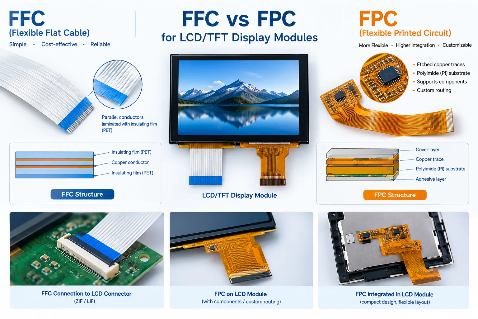
The main difference between FFC vs FPC is their construction and level of circuit integration.
|
Parameter |
FFC (Flexible Flat Cable) |
FPC (Flexible Printed Circuit) |
|
Basic structure |
Flat conductors laminated between insulating films |
Printed/etched copper traces on flexible substrate |
|
Common substrate |
PET or similar insulating film |
Polyimide (PI) or other flexible materials |
|
Circuit complexity |
Standardized parallel conductor layout |
Custom trace geometry, multilayer and shaped routing possible |
|
Components on flex |
Generally no |
Possible |
|
Pitch |
Commonly 0.5 mm, 1.0 mm, 1.25 mm |
Can support fine-pitch custom designs |
|
Flexibility |
Suitable for installation and bending within its specified limits; dynamic bend life depends on the cable design
|
Offers greater freedom in circuit geometry and routing; dynamic flexing requires design-specific bend-life validation |
|
Routing |
Mainly planar |
Customized routing to fit complex layouts |
|
Unit cost |
Often lower for standard configurations |
Often higher when custom geometry, tooling, multilayer construction, or assembly is required |
|
Tooling / NRE |
Often minimal for standard cables |
More likely for custom designs |
|
Typical use |
Standard point-to-point connection |
Dense, compact, or customized interconnection |
In short, FFC is a relatively simple flat cable, while FPC is a flexible circuit that provides greater freedom for electrical and mechanical design.
It is important to note that performance such as temperature range, bend life, and electrical characteristics depends on the specific cable construction and manufacturer specification. These parameters should not be assumed solely from whether the cable is classified as FFC or FPC.
What Is FFC? Flexible Flat Cable
FFC stands for Flexible Flat Cable. It is a flat cable consisting of parallel conductive wires laminated between insulating films. Because the conductors are arranged in a flat, uniform structure, FFCs are commonly used where a compact point-to-point electrical connection is required.
FFC Structure
A typical FFC uses flat copper conductors covered by insulating polymer films. The conductors are exposed at the contact end so that the cable can be inserted into a compatible connector.
Unlike an FPC, an FFC is primarily a cable rather than a flexible circuit board. It normally does not contain electronic components or complex etched circuit patterns along its length.
This relatively simple construction makes FFCs suitable for applications that use standardized cable dimensions and connector interfaces.
FFC for TFT LCD Displays
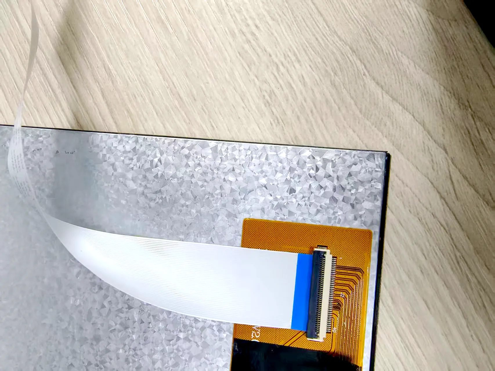
In an LCD/TFT display system, an FFC can provide a point-to-point connection between the display module and the mainboard when the connector and electrical interfaces are compatible. Depending on the module design, the display may have an integrated FPC tail that connects directly to a compatible ZIF/LIF connector on the mainboard, or a separate FFC may be used between compatible connectors on the display assembly and mainboard. The actual configuration depends on the display module design and system architecture.
Common FFC pitches include 0.5 mm, 1.0 mm, and 1.25 mm, although availability varies by manufacturer and product. The required pitch, pin count, cable length, contact orientation, and mating thickness must match the applicable connector specifications.
Advantages of FFC
FFC is often selected because it provides:
- Simple point-to-point electrical connection
- Thin and lightweight construction
- Relatively low unit cost
- Standardized configurations
- Simple integration into compact assemblies
- Availability in common pitches and lengths
For a display that remains in a fixed position and does not require components on the cable, an FFC can be a practical solution.
Limitations of FFC
A standard FFC is primarily designed for electrical interconnection and typically does not integrate electronic components along its length. Its parallel conductor layout is well suited to straightforward connections, but it offers less freedom for customized circuit routing and component integration than an FPC.
Suitability for repeated dynamic bending depends on the specific cable construction and rated bend life. Standard FFCs should not be assumed suitable for repeated dynamic flexing without validation. For applications requiring complex routing, customized circuit patterns, or integrated components, an FPC may offer greater design flexibility.
What Is FPC? Flexible Printed Circuit
FPC stands for Flexible Printed Circuit. Unlike an FFC, an FPC is a flexible circuit board in which conductive traces are formed on a flexible substrate, commonly polyimide (PI).
FPC Structure
An FPC typically consists of copper traces formed on a flexible polyimide substrate, together with insulating and protective layers.
The circuit pattern can be customized to meet the electrical and mechanical requirements of the application. Depending on the design, an FPC can support multilayer routing and components such as resistors, LEDs, connectors, ESD protection devices, or ICs. However, these features are design-dependent and are not present in every FPC.
FPC for LCD/TFT Displays
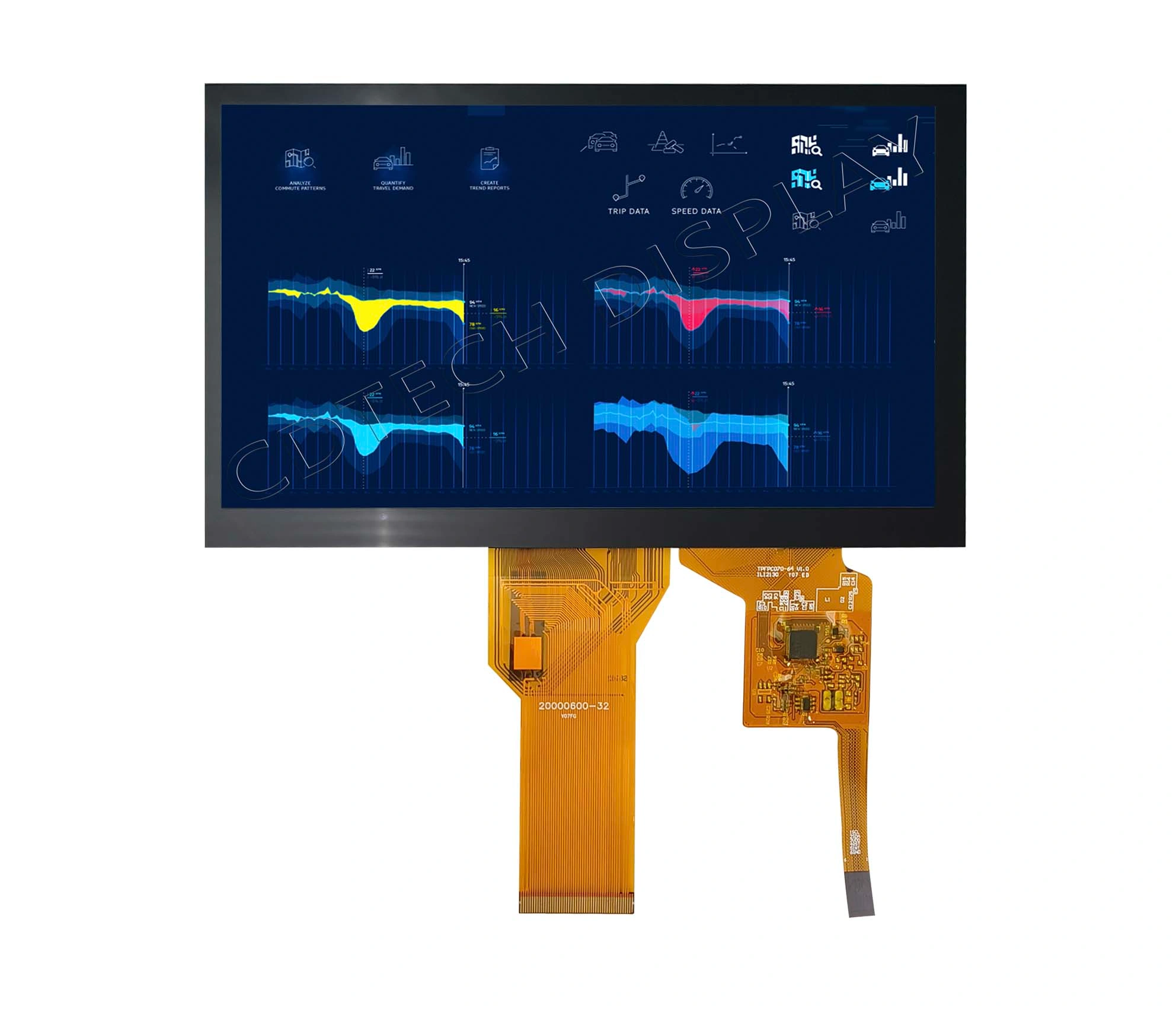
FPCs are widely used in display assemblies where space is limited, routing is complex, or the flexible section needs to accommodate mechanical movement.
For example, an FPC can be routed around a display housing, folded within a compact enclosure, or designed to connect the display to other electronics while following a specific mechanical path.
FPCs are therefore suitable for applications such as:
- Automotive cockpit and instrument displays
- Industrial HMIs
- Portable electronic equipment
- Compact medical devices
- Camera and imaging equipment
- Other space-constrained display assemblies
Advantages of FPC
An FPC can provide:
- Customized circuit routing and geometry
- High-density interconnection and, where required, multilayer designs
- Support for components mounted on the flex
- Greater freedom for compact or irregular mechanical layouts
- Suitability for dynamic bending when specifically designed and validated for the required bend conditions
Limitations of FPC
The additional design flexibility also increases manufacturing complexity.
Compared with a standard FFC, a custom FPC may require more detailed circuit design, tooling, fabrication, and validation. As a result, the unit cost and development effort can be higher.
For a simple display-to-board connection, these additional capabilities may not be necessary.
How Engineers Should Specify the Display Interconnect
The cable type is only one part of the display interconnect design. Connector compatibility, signal requirements, mechanical routing, bend conditions, environmental requirements, and production volume should be evaluated together.
Electrical → Mechanical → Connector → Environment → Cost
How to Choose Between FFC and FPC for an LCD Display?
There is no universal winner in the FFC vs FPC comparison. The appropriate choice depends on the display module and the system in which it will be installed.
Choose FFC When…
FFC is generally a good fit when:
- The display has a static point-to-point connectionto the mainboard.
- A standard cable configuration meets the mechanical requirements.
- No electronic components are needed on the cable.
- The required pitch and pin count are available in a standard configuration.
- The project is sensitive to cable cost.
- The display does not require repeated dynamic bending.
For many standard LCD/TFT assemblies, using an FFC can simplify the interconnection while keeping the cable solution relatively straightforward.
Choose FPC When…
FPC is generally more suitable when the display interconnect requires:
- Customized circuit routing or shaped geometry to fit the enclosure.
- High-density interconnections or complex pin assignments.
- Components integrated onto the flexible circuit, where supported by the design.
- Multilayer routing or other circuit features that a standard FFC cannot provide.
- A customized electrical and mechanical interface for a specific product design.
- Repeated dynamic bending, provided the FPC is specifically designed and validated for the required bend radius, movement, and cycle life.
For applications involving repeated movement, such as displays installed near hinges or moving mechanisms, a purpose-designed FPC or specialized FFC may be appropriate. The final choice should be based on the cable construction, copper design, bend radius, strain relief, and required bending-cycle life rather than the cable category alone.
For automotive, industrial, medical, and other specialized display applications, a customized FPC can be useful when the display interface must fit a specific mechanical and electrical architecture.
How to Specify an FFC or FPC for Your TFT Display
Once you know whether an FFC or FPC is appropriate, several parameters should be defined before ordering or designing the LCD/TFT display module.
1. Pitch
FFC pitch refers to the center-to-center distance between adjacent conductors.
Common configurations include:
- 5 mm
- 0 mm
- 25 mm
The cable pitch must match the mating connector. A cable with the correct number of pins but the wrong pitch will not be compatible with the connector.
2. Pin Count and Cable Length
The number of conductors must match the required signal connections.
Cable length should also be specified according to the actual distance between the display and mainboard. Avoid selecting a cable that is unnecessarily long, particularly when the display interface involves higher-speed signals.
3. Connector Type and Orientation
Connector compatibility involves more than pitch.
Engineers should also check:
- ZIF or LIF connector
- Contact side
- Contact orientation
- Straight or right-angle configuration
- Connector location
- Cable insertion direction
A cable can have the correct pitch and pin count and still fail to mate correctly if its contact orientation does not match the connector.
Connector selection is another important consideration when integrating a display module. Depending on the system architecture, engineers may need to compare an FPC connector with a board-to-board connection to meet mechanical, electrical, and space constraints. See our guide to FPC vs. board-to-board connector selection for more details.
4. Bend Requirements
Determine whether the cable will experience static or dynamic bending.
Static bending occurs when the cable is bent during installation and remains in a relatively fixed position. Dynamic bending involves repeated movement during product operation and places different fatigue demands on the conductors and flexible substrate.
For dynamic applications, specify the minimum bend radius, movement pattern, required cycle life, and mechanical constraints. The cable supplier should confirm whether the selected FFC or FPC construction is suitable for these conditions.
Bend life depends on factors such as copper construction, substrate materials, layer stack-up, bend radius, routing, and strain relief. Neither FFC nor FPC should be assumed suitable for repeated dynamic bending based on its category alone. The final design should be validated under representative operating conditions.
5. Temperature Rating
The required operating temperature depends on the target application.
Consumer products may have relatively moderate environmental requirements, while industrial, outdoor, medical, and automotive equipment may require a wider operating temperature range.
The complete cable specification should be checked for the intended temperature range. Material type alone does not define the operating temperature capability of a finished FFC or FPC assembly.
6. Shielding and EMI Considerations
For EMI-sensitive display systems, shielding and grounding may also need to be considered.
Industrial and medical equipment can contain motors, switching power supplies, communication modules, or other potential interference sources. Cable routing, grounding, shielding, connector design, and display interface should therefore be evaluated as part of the complete system.
7. Mating Thickness and Stiffener
The mating thickness of the FFC or FPC must match the connector specification. For FPCs, a stiffener may also be required at the connector interface to provide the correct insertion thickness and mechanical stability. These dimensions should be confirmed from the connector and FPC/FFC drawings before production.
Common FFC/FPC Problems in Display Systems
Problems with the flexible cable or connector can sometimes appear as display failures.
Reversed Pinout or Connector Orientation
An incorrect pinout or reversed contact orientation may cause:
- Blank display
- Incorrect image output
- Unstable display operation
- Non-functional touch interface
Always verify the cable pinout and connector orientation against the display and mainboard drawings.
Connector Pitch Mismatch
Pitch must match between the cable and connector.
For example, a 0.5 mm-pitch cable and a 1.0 mm-pitch connector are not interchangeable simply because the two cables have similar pin counts.
Excessive Bending or Mechanical Stress
Sharp folds, excessive bending, or concentrated stress near the connector can damage the conductors or cause intermittent electrical connections.
The cable should be routed with an appropriate bend radius and secured so that mechanical stress is not transferred directly to the display tail or connector.
Cable Length and Signal Integrity
Cable length and construction can affect signal integrity, particularly in high-speed display interfaces. For interfaces such as MIPI DSI, LVDS, and eDP, engineers should evaluate impedance, differential-pair routing, grounding, connector discontinuities, cable length, and EMI control together.
The cable type alone does not guarantee signal integrity. The complete interconnect should be validated for the target interface, data rate, and system configuration.
EMI on Unshielded Cables
Unshielded cables can be more susceptible to electromagnetic interference depending on the surrounding environment.
If the display is installed close to motors, power electronics, or other EMI sources, cable routing and shielding should be addressed during the design stage.
Wrong Mating Thickness
The FFC or FPC mating thickness must fall within the range specified for the connector. If the cable is too thick, it may be difficult to insert fully or the connector locking mechanism may not close correctly. If it is too thin, the connector may not provide sufficient contact pressure or retention, potentially causing intermittent electrical connections.
For an FPC, a stiffener may be required at the contact area to achieve the specified mating thickness and improve mechanical stability. However, the required thickness and stiffener configuration depend on the connector design.
Before production, verify the cable thickness, contact finish, stiffener dimensions, and connector specifications. Proper strain relief should also be provided to minimize mechanical stress near the connector transition.
Custom FFC/FPC Solutions for LCD Modules from CDTech
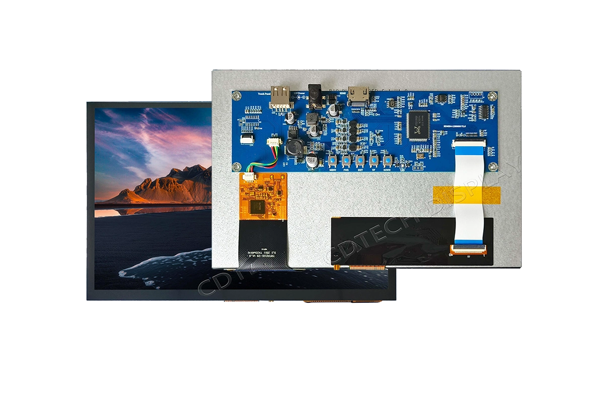
For a customized LCD/TFT display, the flexible cable is part of the overall display interface and should be considered together with the panel, touch solution, connector, and mechanical structure.
CDTech supports both standard FFC-based and customized FPC-based LCD configurations depending on the display interface and mechanical requirements. Standard products may use FFC connections for straightforward integration, while custom FPC designs can be developed when the project requires specific pinouts, routing, connector positions, shielding, or mechanical dimensions.
CDTech display solutions are used in applications including:
- Industrial HMI
- Medical equipment
- Automotive cockpit and EV displays
- Outdoor display equipment
- Customized embedded display systems
If your project requires a display module with a specific FFC/FPC interface, contact the CDTech engineering team to discuss the required display size, interface, cable configuration, and application environment.
When standard cable configurations cannot meet the required pinout, routing, or mechanical layout, a customized flex circuit may offer greater design flexibility. Learn more about custom FPC LCD module design for industrial, automotive, and medical applications.
Frequently Asked Questions
Q1: Is FFC the same as FPC?
A: No. An FFC is a flexible flat cable, while an FPC is a flexible printed circuit. FFCs generally use parallel conductors laminated between insulating films, while FPCs use patterned conductive traces on a flexible substrate and can support more complex routing and component integration.
Q2: Which is better for an LCD display?
A: It depends on the application. FFC is generally suitable for straightforward, static, cost-sensitive connections using standard configurations. FPC is often preferred when customized routing, shaped geometry, high-density interconnection, or component integration is required. For repeated dynamic bending, select an FFC or FPC specifically designed and validated for the required bend radius and cycle life.
Q3: Can I use an FPC in place of an FFC?
A: An FPC can potentially perform the same electrical connection function, but it is not necessarily a direct mechanical replacement. Pitch, pin count, contact orientation, connector type, dimensions, and electrical requirements must all be compatible. A custom FPC may also involve additional tooling and manufacturing costs.
Q4: What pitch should my display cable be?
A: The cable pitch must match the connector used by the LCD/TFT module and mainboard. Common configurations include 0.5 mm and 1.0 mm, but the correct specification depends on the actual display interface. Always confirm the connector drawing before selecting an FFC or FPC.
Q5: Can the same connector accept both FFC and FPC?
A: Some connectors are specifically designed to accept either FFC or FPC, but compatibility cannot be assumed. Engineers should verify the connector datasheet for supported cable type, mating thickness, pitch, contact side, and retention requirements.
Conclusion
The choice between FFC and FPC for a TFT LCD display module should be based on the actual requirements of the product rather than simply on cable type.
Choose FFC for straightforward, cost-effective connections that meet the requirements of a standard cable configuration. Choose FPC when the design requires customized routing, shaped geometry, high-density interconnection, or component integration. For repeated dynamic bending, either a purpose-designed FPC or a specialized FFC may be suitable, provided its bend-life performance is validated for the intended application.
Before finalizing the display module, verify the pitch, pin count, cable length, connector type, contact orientation, bend requirements, temperature rating, shielding, and signal-integrity requirements.
A correctly specified flexible cable can make display integration much easier and help avoid common problems such as connector incompatibility, intermittent signals, mechanical damage, and unnecessary redesign.
Need a custom LCD/TFT display with an FFC or FPC interface?
Share your display size, resolution, interface, connector specification, pin count, cable length, bend requirements, and operating temperature with the CDTech engineering team. We can evaluate the display and interconnect configuration based on your mechanical and electrical requirements.
