

What Is In-Cell Touch Display Technology? A Guide to TFT LCD Applications
 2026-09-30
  11:24
11:24 

As device designers pursue slimmer modules and better optical integration, touch architectures such as Out-Cell, On-Cell and In-Cell provide different trade-offs in thickness, integration, touch performance and development complexity.
This guide explains Out-Cell, On-Cell and In-Cell, clarifies the difference between In-Cell and TDDI, and outlines key factors for selecting an In-Cell TFT LCD.
What Is In-Cell Touch Display Technology?
In-Cell touch display technology is a TFT LCD architecture in which the touch-sensing structure is integrated within the LCD cell rather than implemented as a separate external touch sensor.
Depending on the panel architecture, touch electrodes can be integrated into different layers of the LCD cell and designed to work with the display driving system. This integration can reduce external touch layers, support a thinner module profile and improve optical efficiency by reducing additional optical interfaces.
Unlike traditional Out-Cell configurations, In-Cell combines display and touch functions more closely within the panel structure, but the exact electrode layout and sensing method vary by panel design.
How In-Cell Works: Touch Sensing and TDDI
Touch Sensing and Time-Division Operation
Some In-Cell architectures use time-division techniques to separate display driving and touch sensing within the same frame period. Different time slots are allocated to display operation and touch sensing to help manage interference between the two functions.
The exact implementation depends on the LCD electrode structure, touch-sensing method and controller architecture.
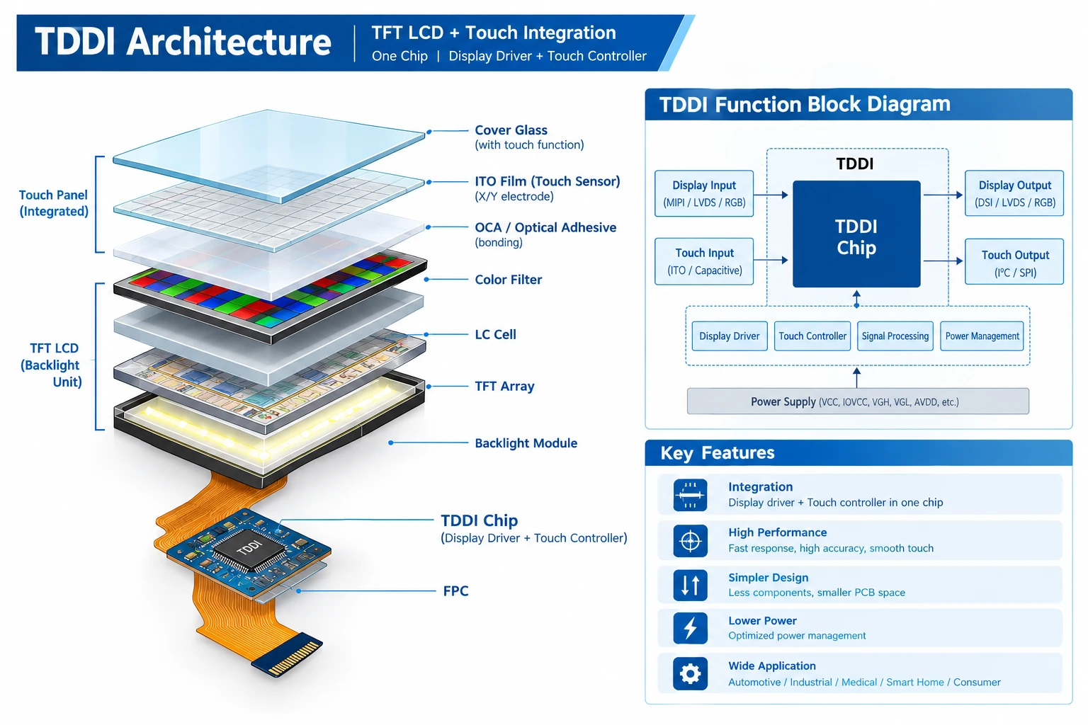
TDDI Architecture
TDDI (Touch and Display Driver Integration) combines the touch controller and display driver functions into a single IC. TDDI can be used with certain In-Cell architectures to reduce component count, simplify routing and improve coordination between display driving and touch sensing.
In-Cell and TDDI describe different aspects of the system: In-Cell refers to the physical integration of the touch-sensing structure within the display cell, while TDDI refers to the integration of touch and display driver functions in the IC.
The appropriate touch IC and configuration depend on the panel structure, interface requirements, cover-glass thickness and target touch performance.
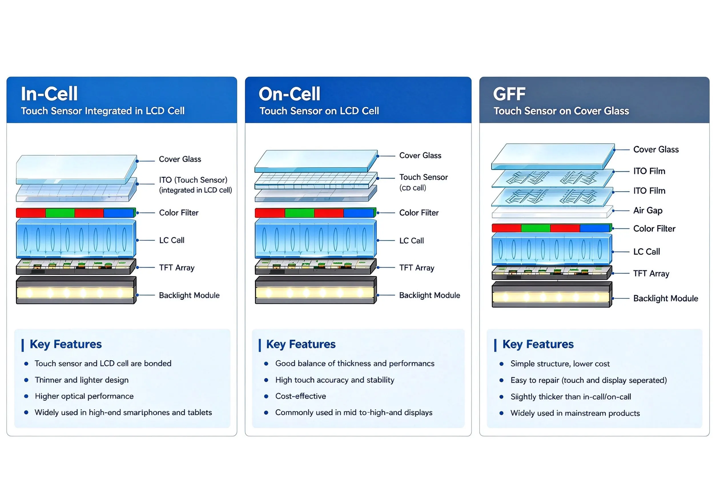
Mainstream Touch Stack Architecture: Out-Cell, On-Cell and In-Cell
Traditional touch screens rely on separate touch sensor layers stacked on top of the LCD module. As the industry evolved, integrated touch structures emerged to cut thickness and simplify BOM.
Out-Cell
Out-Cell uses a standalone touch panel bonded externally to the LCD module. It covers four sub-categories: OGS, G+F, G+FF and G+G. CDTech provides G+FF and G+G Out-Cell touch modules, which deliver robust reliability for harsh working-environment applications.
GFF (Glass-Film-Film)
GFF (Glass-Film-Film / Out-Cell): A traditional structure in which a separate touch panel is bonded to the LCD. Its multi-layer construction generally increases module thickness and adds optical interfaces compared with integrated touch architectures.
On-Cell
On-Cell: Places the touch-sensing structure on the upper substrate of the display cell. It can reduce stack thickness compared with many Out-Cell configurations, but touch performance and manufacturing complexity depend on the panel architecture and process.
In-Cell
In-Cell technology integrates the touch sensing structure within the LCD cell, eliminating the need for a separate external touch sensor panel.
- Potential benefits: A more integrated module structure can reduce the number of external touch layers, help reduce module thickness, minimize additional optical interfaces and support a cleaner front-stack design.
- Considerations: Because the touch sensing structure is integrated within the LCD cell, electrical noise from display operation must be carefully managed to maintain stable touch detection. The touch sensing architecture, controller configuration and signal tuning therefore need to be designed for the specific panel implementation. The integrated structure can require more specialized panel fabrication and touch-sensing integration. It may also make component-level repair or replacement more complex than a discrete touch-panel architecture.
Touch Technology Decision Matrix: In-Cell, On-Cell, Out-Cell
Selecting the proper touch stack is critical for industrial, automotive and consumer display projects. The three main touch architectures are In-Cell, On-Cell and Out-Cell. Out-Cell covers four sub-categories: OGS, G+F, G+FF and G+G. CDTech mainly supplies G+FF and G+G variants. The table below compares their touch sensor placement, module thickness, optical performance, reliability, BOM cost and typical applications.
|
Item |
In-Cell |
On-Cell |
Out-Cell (OGS, G+F, G+FF, G+G) |
|
Touch Sensor Placement |
Integrated within the LCD cell, with touch electrodes incorporated into the cell structure |
Integrated on the upper glass substrate of the LCD |
Separate touch panel bonded to the LCD module |
|
Module Thickness |
Generally thinner due to fewer external touch layers |
Can be thinner than many Out-Cell configurations |
Generally thicker due to separate touch-panel components |
|
Light Transmittance & Reflection |
Fewer external optical interfaces can improve optical efficiency. |
Fewer external layers than many Out-Cell configurations. |
Additional touch layers and bonding interfaces may increase reflection and optical loss. |
|
Environmental Reliability |
Fewer external touch interfaces; reliability depends on panel construction and process control |
Depends on sensor structure, bonding and panel construction |
Bonding interfaces require validation for delamination, bubbles and environmental aging |
|
Touch Performance |
Good; highly dependent on sensor integration, controller selection and noise tuning |
Good; provides a balance between integration and touch performance |
Mature and flexible; performance can be optimized through sensor structure, controller selection and bonding configuration |
|
BOM & Development Cost |
Potentially lower module-level BOM, but higher engineering/NRE for customized designs |
Cost depends on panel architecture, production volume and development requirements |
Additional touch-panel components and bonding can increase module and assembly costs |
|
Typical Use Cases |
Smart-home panels, consumer electronics and other high-volume products requiring thinness and high integration |
Consumer electronics, compact commercial displays and applications requiring a balance of integration and flexibility |
Industrial HMI, medical equipment, automotive displays, marine equipment and rugged-environment applications |
Key Benefits of In-Cell Touch Technology
Touch Performance
With appropriate sensor design, touch-controller selection and signal tuning, In-Cell displays can support glove-touch and wet-finger operation in suitable applications. Actual performance depends on the panel architecture, touch IC, cover-glass structure and system-level noise environment.
- Wet-Finger and Water-Rejection Performance: Touch detection can be tuned for water droplets and wet-finger conditions according to the target application.
- Glove Touch Compatibility: Sensitivity and scanning parameters can be optimized for glove operation. The achievable glove thickness depends on the touch IC, cover glass, glove material and system tuning.
System Integration
By integrating touch sensing into the LCD cell, In-Cell reduces the need for a separate touch sensor panel and its associated assembly interfaces. This can simplify module integration and supply-chain management.
Cost & Development Considerations
The economic impact depends on production volume, panel architecture and development requirements. High-volume production may benefit from fewer external components and assembly steps, while customized projects can require higher engineering and NRE investment.
Engineering Considerations for Industrial & Automotive Applications
For industrial or automotive applications, In-Cell touch performance should be evaluated at the complete system level.
- Touch performance:Validate glove touch, wet-finger operation, touch SNR and response under the target system noise conditions.
- Temperature:Match the panel’s operating and storage temperature range with the application requirements.
- EMI/EMC:Evaluate the complete display, FPC, controller, grounding and host system rather than relying on the touch architecture alone.
- Mechanical reliability:Consider cover-glass thickness, mounting structure, vibration and environmental requirements.
For rugged or highly customized projects, Out-Cell G+FF/G+G may provide greater flexibility in touch-sensor and mechanical design. The appropriate architecture depends on the application’s environmental, mechanical, touch and production requirements.
What Should Engineers Consider When Selecting an In-Cell Touch LCD?
In-Cell touch LCDs integrate touch sensing directly within the LCD cell, eliminating external touch layers to support thinner, more optically integrated module designs.
Core Selection Factors
1. Display & Optical Performance
- Display Size & Resolution:Confirm panel dimensions, outline footprint, and pixel density to match your enclosure design and UI clarity requirements.
- Viewing Angle & Brightness: IPS panels are commonly used where wide viewing angles are required. Select luminance based on ambient light and indoor or outdoor operating conditions.
2. Touch & System Integration
- Display & Touch Interfaces:Verify compatibility between host SoC and interfaces (MIPI, RGB, eDP for display; I²C, SPI for touch).
- Touch Performance & EMI:Evaluate SNR, touch points, latency, glove/wet-touch support, and electromagnetic interference (EMI) handling under noisy system environments.
- Operating Temperature:Match working and storage temperature ranges to industrial or automotive grade requirements.
3. Mechanical & Customization
- Module Thickness:Compare total stack height (LCD, internal touch structure, adhesive, backlight, and cover glass) against enclosure limits.
- Cover Glass & Surface Treatments:Select glass thickness, 2.5D edges, and protective coatings (AG anti-glare, AF anti-fingerprint) according to application demands.
- Customization & Logistics:Confirm custom FPC design, cover glass lens printing, MOQ, and procurement lead times prior to project lock.
Bonding Methods for Touch Display Modules
Frame bonding and optical bonding are assembly methods rather than touch-sensing architectures. They can be applied to different touch/display configurations depending on the module design.
- Frame Bonding: Leaves an air gap between the touch structure/cover glass and LCD, which can increase internal reflections and parallax.
- Optical Bonding: Uses optically clear adhesive (OCA/OCR) to eliminate the air gap, reducing internal reflections and improving optical integration.
- In-Cell: Because the touch-sensing structure is integrated into the LCD cell, it eliminates the need to bond a separate touch sensor panel to the LCD. Cover-glass bonding may still be used depending on the module design.
CDTech In-Cell LCD Display Solutions
CDTech develops In-Cell touch TFT LCD modules with display and touch interfaces configured according to the requirements of each product architecture.
Compact In-Cell Touch LCD Displays
 |
 |
|
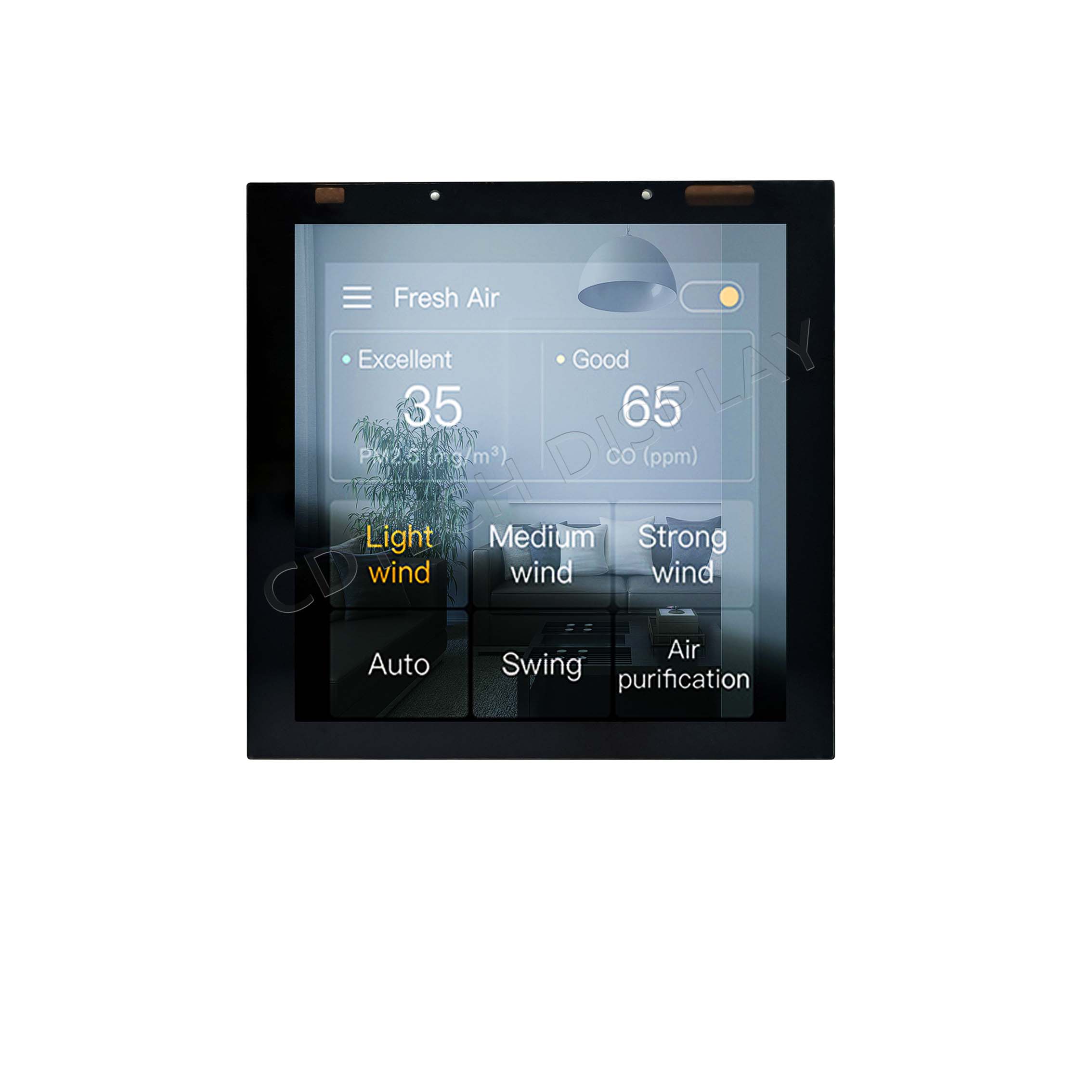
4.0-Inch 480×480 IPS In-Cell Touch LCD
Model:S040YWV20HN-FL19-AF
480 × 480 | IPS | MIPI | I²C Touch | 450 nits
|
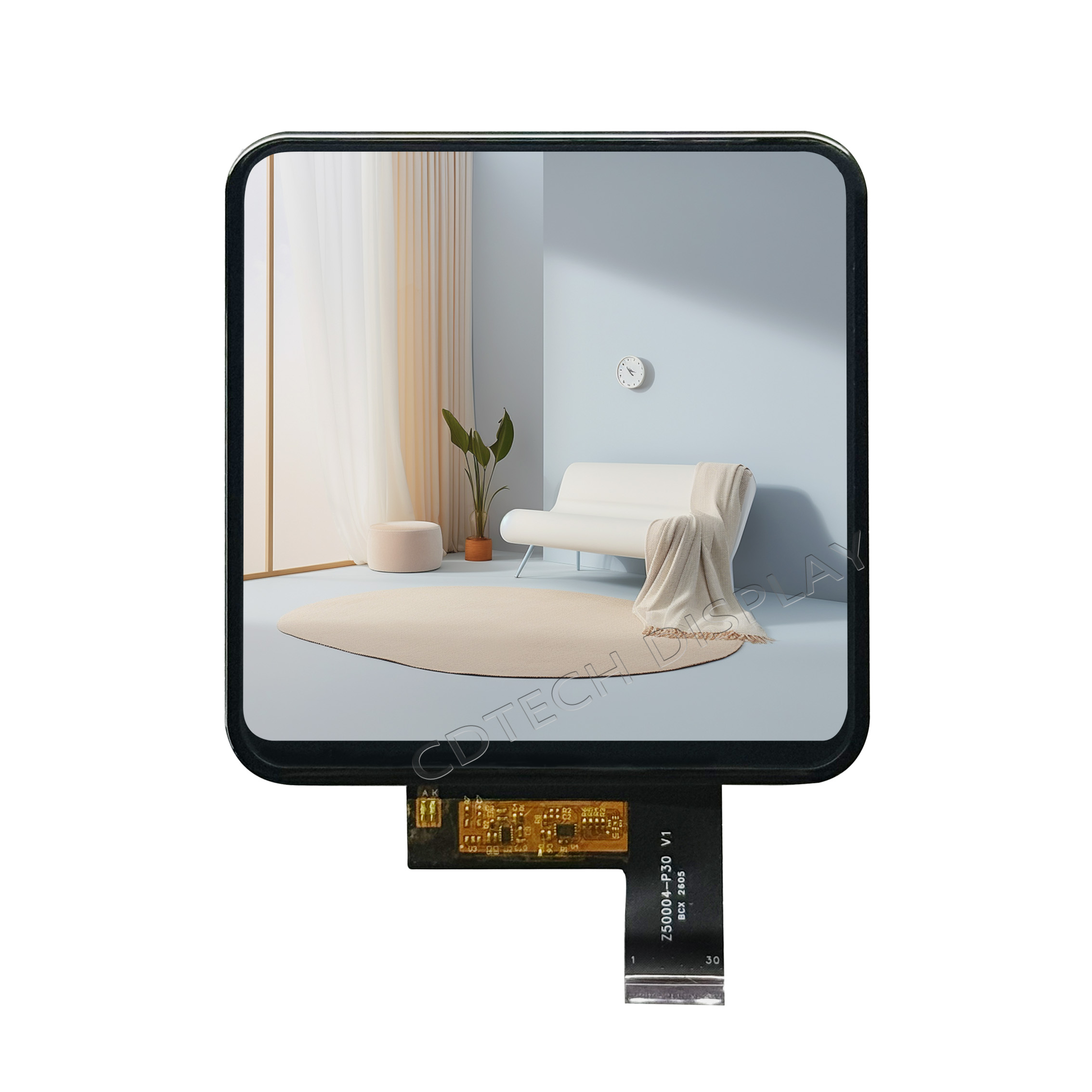
5.0-Inch 720×720 IPS In-Cell Touch LCD
Model:S050IWX126NN-FC101-FD
720 × 720 | IPS | MIPI | I²C Touch | 500 nits
|
Large-Format In-Cell Touch TFT LCD Displays
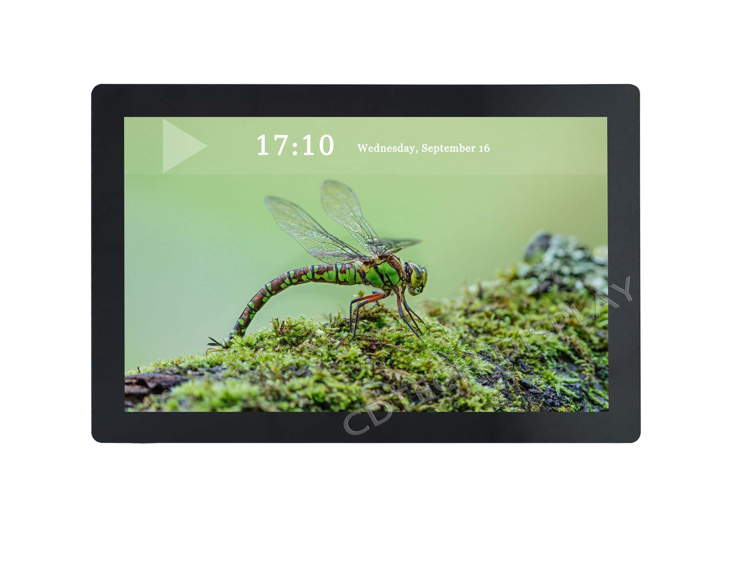
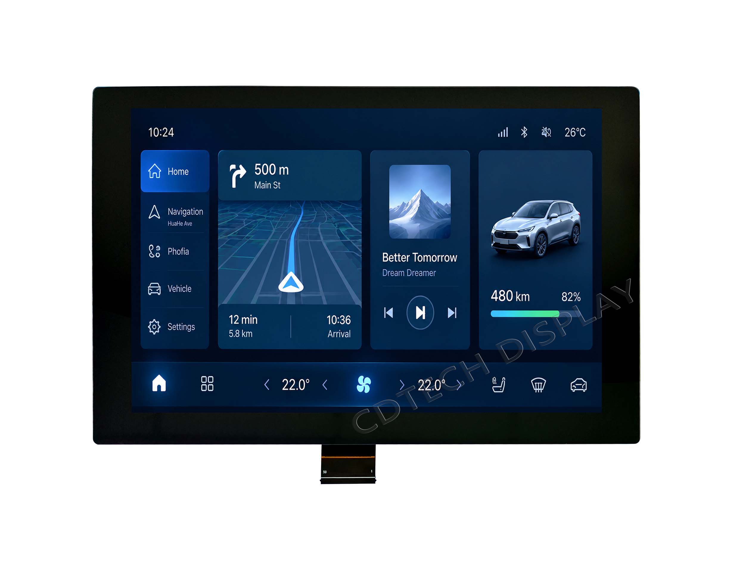
For larger interactive interfaces, CDTech offers 10.1-inch In-Cell TFT LCD solutions for embedded interactive projects. The two configurations share a 1280×800 IPS display format but are optimized for different system requirements.
 |
 |
|
10.1-Inch 1280×800 In-Cell IPS Display
Model: S101ZWX109HP-FC69
1280 × 800 | IPS | LVDS | I²C Touch | 1000 nits
|
10.1-Inch 1280×800 Custom In-Cell Display
Model: S101ZWX108EP-FC70-AG
1280 × 800 | IPS | LVDS | I²C Touch | 850 nits
|
Why Choose CDTech In-Cell LCD Displays?
- Defined Size Capabilities & Fast Prototyping: CDTech currently supports In-Cell touch module development from approximately 4.0 to 10.1 inches, with larger sizes available for custom evaluation.
- Application-Specific Touch Tuning: We can fine-tune glove touch (up to 3 mm thick) and wet-finger / water-rejection performance according to project requirements, with wide-temperature display configurations available for industrial applications.
- End-to-End Optical & Cover Lens Integration: In-house support for custom Cover Glass (up to 6mm thickness with AG/AR/AF coatings) and direct optical bonding support with LOCA/OCA to improve optical integration and reduce reflections in high-brightness display applications.
Commercial & Technical Support
- Rapid Prototyping: Engineering samples delivered within 3–4 weeks for standard optical configurations.
- Flexible MOQ: Low MOQ support for pilot production runs and NPI (New Product Introduction) phases.
- Dedicated FAE Support: Direct 1-on-1 support from CDTech display engineers for firmware tuning, TDDI IC selection, and system interface debugging (MIPI DSI / LVDS).
Applications of In-Cell LCD Displays
CDTech’s In-Cell touch TFT LCD displays are suited to high-volume embedded applications where thinness, optical efficiency and touch/display integration are important. Typical applications include:
- smart-home control panels
- Home appliances
- Handheld POS terminals
- Gaming devices
- IoT embedded devices
Industry Trends and Challenges
In-Cell is well established in small-to-medium display applications, while scaling to larger formats can introduce challenges such as RC delay, touch SNR management and signal routing complexity.
CDTech currently focuses on In-Cell solutions up to 10.1 inches, with larger formats available for custom evaluation.
Frequently Asked Questions
Q1: What is the difference between In-Cell, On-Cell and Out-Cell?
A: The core distinction is touch-sensor placement. Refer to the Touch Technology Decision Matrix table above for full side-by-side comparison of thickness, optics, reliability and use-cases.
Q2: Can In-Cell touch screens support glove touch, wet-finger operation and thick cover glass?
A: Yes. In-Cell displays can be designed and tuned for glove touch and wet-finger operation. Support for thicker cover glass depends on the touch IC, sensor architecture and system noise environment. CDTech can evaluate cover glass up to 6 mm and glove operation up to 3 mm according to project requirements and test conditions.
Q3: Is In-Cell touch technology suitable for outdoor high-brightness TFT LCDs?
A: In-Cell can be suitable for high-brightness display applications because its integrated structure can reduce additional optical interfaces and associated reflections. However, sunlight readability depends on the complete optical stack, including display brightness, reflectance, cover glass, surface treatment and bonding. A brightness level of 1000 nits or higher can support outdoor readability, but it should not be considered a standalone guarantee of sunlight readability.
Q4: How does In-Cell touch technology impact overall manufacturing costs?
A: In-Cell can reduce external touch components and certain assembly steps, which may provide system-level integration and cost benefits in high-volume production. However, development and NRE costs can be higher, particularly for customized low-volume projects. Therefore, total project cost should be evaluated based on both development investment and production volume.
Q5: What is CDTech’s typical lead time and MOQ for custom In-Cell touch displays?
A: Standard sample lead time is typically 3–4 weeks. We support flexible MOQs for early-stage engineering evaluation and industrial projects requiring long-term supply stability (5–7 years).
Q6: Can In-Cell technology be used with different TFT LCD panel types?
A: In-Cell implementations can be developed for different TFT LCD architectures, but feasibility depends on the panel electrode structure, touch-sensing method, controller and manufacturing process. IPS-based architectures are commonly used in applications requiring wide viewing angles, while the final configuration should be evaluated according to the display and touch requirements of the project.
Get In Touch About Your In-Cell Display Project
Looking for an In-Cell Touch TFT LCD for your next embedded display project?
Contact CDTech’s engineering and sales team for datasheets, samples and customization options. Depending on project requirements, we can discuss display size, resolution, interface, brightness, cover glass, touch configuration, operating temperature and mechanical requirements.
There is no universal best touch architecture. The appropriate solution depends on target thickness, optical requirements, mechanical reliability, touch performance, manufacturing requirements and project cost.
Post Search
Related Articles
-

Capacitive vs Resistive Touch Screen Car Stereo: Which Is Right for You?
-

TN LCD vs IPS LCD: How to Choose the Right Display for You
-

Capacitive Touch Panel or Resistive: Which Suits Your Needs?
-

Why Choose an IPS LCD Panel for Your Next Screen Purchase?
-

CDTECH to Showcase Cutting-Edge Display Solutions at SID 2025
-

Comparing Different Types of Displays in Cars: A Detailed Overview
-

White Spots on LCD Screen: Causes, Fixes & Industrial Solutions (2026 Guide)