Step-by-Step Installation of a Capacitive Touch Switch Panel
 2026-09-17
  10:00
10:00 


What Should Be Checked Before Installing a Capacitive Touch Switch Panel?
A capacitive touch switch panel joins a sensing layer, cover surface, display or indicator, cable assembly, and host controller. A successful installation depends on matching all of those elements before adhesive, screws, or power are applied. The installer should treat capacitive touch panel technology as part of a complete electrical and mechanical system, rather than as a loose front surface.
Which Interface, FPC, and Power Details Must Match?
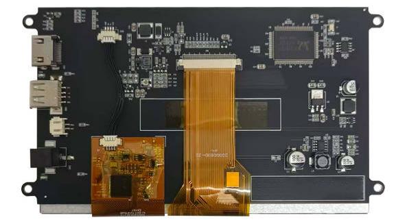
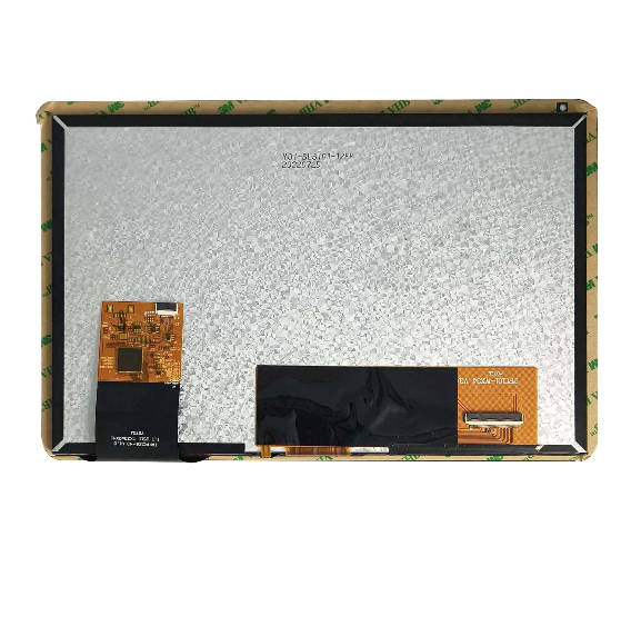
Start with the approved drawing and confirm the LCD interface, touch interface, connector pitch, pinout, cable direction, supply voltage, and ground reference. Capacitive modules may pair RGB LCD interfaces with I2C or IIC touch connections, while the touch controller varies by model. A custom capacitive touch display brief should identify every connection instead of relying on a generic connector label.
The host controller also needs a defined initialization sequence and touch-coordinate orientation. Before physical installation, compare the panel drawing with the host schematic, check cable reach, and identify any exposed conductive frame that could affect sensing. A continuity check with power removed can catch a reversed cable or short before a valuable sample is connected.
How Should the Enclosure and Touch Surface Be Prepared?
Measure the opening, bezel step, mounting points, cover thickness, and cable exit. Remove burrs and dust from the enclosure, then verify that the bezel supports the panel without pressing the active area. Clean the cover surface with a compatible lint-free method. Avoid solvents or tools that can damage an AG, AF, or AR finish.
For custom capacitive touch panels, the outline, cover-lens shape, adhesive land, and FPC bend radius should be frozen in the mechanical drawing. A custom capacitive touch screen may use a different glass thickness, bonding stack, or mounting feature than a standard reference, so a dry fit remains essential before permanent fixing.
How Do You Install and Connect the Capacitive Touch Switch Panel Step by Step?
The capacitive touch switch panel installation sequence should protect the active area, keep the cable path controlled, and create a clear inspection point before first power-on. The following sequence works as a project checklist; exact torque, adhesive, and clearance values must come from the approved drawing for the selected panel.
What Are the Dry-Fit, Clean, Secure, and Cable-Connection Steps?
1.Place the unpowered panel into the opening and confirm orientation, bezel support, and cable clearance.
2.Remove the panel and clean the mating surfaces. Keep particles away from the optical area and adhesive land.
3.Refit the panel without forcing the glass. Secure the approved edges or fasteners, keeping pressure away from the active area.
4.Route the FPC with the specified bend radius. Do not fold across the connector or pull the cable tight.
5.Connect LCD and touch cables separately when the design uses separate interfaces. Lock each connector and inspect for skew.
6.Confirm grounding, strain relief, and enclosure clearance before applying power.
This sequence helps a team identify a mechanical problem before a touch fault becomes difficult to isolate. A custom capacitive touch display installation should also record the sample revision, drawing revision, and cable configuration used during assembly.
How Should Capacitive Touch Panel Technology Be Verified After Power-On?
Apply power only after polarity, voltage, ground, and connector seating have been checked. First verify a stable image or indicator state. Next confirm that the host detects the touch controller, then test single points across the active area. Check edge response, repeated taps, swipe tracking, and coordinate orientation. Record whether false touches appear when the display cable, backlight, or nearby motor starts.
The purpose of this sequence is fault isolation. A blank image points toward the display path or power path; a visible image with no touch response points toward the touch cable, controller initialization, grounding, or firmware; an offset response points toward coordinate mapping or mechanical alignment. This is a practical way to verify capacitive touch panel technology without claiming that one test proves long-term reliability.
Which Installation Risks Change for Automotive and Custom Capacitive Touch Panels?
An installed capacitive touch switch panel experiences more than bench conditions. Vibration, sunlight, temperature cycling, moisture, gloves, cleaning chemicals, and electromagnetic noise can change the validation plan. The installation team should connect every risk to a test condition and a pass criterion.
When Does an Automotive Capacitive Touch Panel Need Extra Validation?
An automotive capacitive touch panel needs application-specific review when the assembly will face direct sunlight, wide temperature changes, vibration, glove operation, or frequent cleaning. Relevant model configurations may combine high brightness, IIC touch with HDMI or LVDS display interfaces, surface coatings, EMI-shielded FPC, and defined operating ranges. These are fields to verify for the selected model, not a universal automotive specification.
The validation plan can include powered vibration checks, touch tests with expected gloves, display readability at the intended viewing angle, connector retention, and inspection after cleaning exposure. EMI and ESD requirements should be stated by the host-system team so the panel, cable, and enclosure are reviewed together.
When Should Buyers Move From Standard Installation to Custom Capacitive Touch Panels?
Move toward custom capacitive touch panels when the opening is non-standard, the bezel is narrow, the cover needs a special shape or treatment, the FPC must exit in an unusual direction, or the interface cannot match a catalogue configuration. A custom capacitive touch factory request becomes meaningful when the buyer supplies drawings, touch behavior, environmental conditions, test criteria, and expected quantities.
Customization should solve a defined integration problem. A larger cover, different bonding method, or revised connector can affect optics, touch sensitivity, assembly yield, and service access. Each change should therefore be reviewed through sample inspection and documented revision control.
How Can CDTech Support a Capacitive Touch Switch Panel Installation?
At CDTech, we help buyers turn a capacitive touch switch panel requirement into a reviewable LCD and touch configuration. We can discuss LCD/CTP coordination, cover-lens geometry, bonding, FPC layout, interface definition, and environmental test inputs as connected engineering decisions. Our verified references include capacitive touch modules with model-specific LCD interfaces, I2C or IIC touch connections, and documented operating conditions.
What Can CDTech Review Before a Custom Capacitive Touch Display Quote?
We review the enclosure drawing, active area, resolution, luminance, host interface, touch controller, cover treatment, bonding preference, cable direction, operating environment, and target quantities. A custom capacitive touch display enquiry becomes easier to evaluate when the buyer also sends the host schematic, intended cleaning method, glove requirement, and sample acceptance criteria.
Which CDTech Evidence Helps De-Risk Installation?
The S070SWV95HD-DC128 provides one installation reference: its 7-inch, 800 x 480 LCD uses RGB, while the capacitive touch panel uses I2C with a GT911 controller. These defined paths help buyers compare host compatibility, connector routing, and enclosure fit before sample approval. We can then identify whether a custom capacitive touch factory route is needed for the final host-system requirements.
FAQ
Q: What Must Be Checked Before Installing a Capacitive Touch Switch Panel?
A: Check the approved drawing, LCD and touch interfaces, pinout, voltage, ground, connector direction, bezel support, cover finish, cable bend radius, and environmental conditions. A dry fit and continuity check should come before permanent fixing or power-on.
Q: When Is a Custom Capacitive Touch Screen Better Than a Standard Panel?
A: A custom capacitive touch screen is useful when the outline, cover lens, mounting, bonding, FPC, interface, or environmental requirement cannot be met by a standard panel. The brief should define the specific integration problem and the test conditions.
Q: Does an Automotive Capacitive Touch Panel Need Different Tests?
A: Yes. An automotive capacitive touch panel should be checked against the vehicle environment, including sunlight, temperature, vibration, gloves, cleaning chemicals, EMI/ESD, connector retention, and viewing angle. Model-specific evidence should guide the test plan.