Exploring USB Interface Options for Seamless Display Connectivity
 2026-09-03
  10:00
10:00 

USB is now common in display assemblies, but the label does not always mean that a panel accepts native USB video. In one project, a USB interface may carry touch data, connect a controller, support service access, or work through a bridge board while the LCD image still travels over LVDS, RGB, HDMI, or another path. Understanding that distinction helps OEM teams choose the right module, cable, driver, and validation plan. This guide explains how to compare USB with SPI and I2C, when an I2C to USB converter may be considered, and how to qualify a USB LCD panel without turning a convenient connector into an unsupported performance claim.
What Does a USB Interface Do in a Display System?
Is USB a Native LCD Video Interface or a Bridge Path?
A USB interface is a physical and logical connection whose role depends on the controller and board design. A complete display assembly can use LVDS for LCD pixels and USB for the capacitive touch controller. Another assembly can use an HDMI board for video and USB for touch. A third design may use a bridge that translates a host signal into the timing expected by the panel. Therefore, an OEM should ask what the USB port carries, which device enumerates, and which driver the host must install before calling a product a USB display.
The phrase USB LCD panel should be treated as a project description rather than a universal electrical standard. A panel record needs separate fields for LCD interface, touch interface, controller, connector, cable, power, and operating conditions. This separation prevents a buyer from assuming that a USB cable can replace every display timing or power requirement.
Which Signals Can a USB Connection Carry?
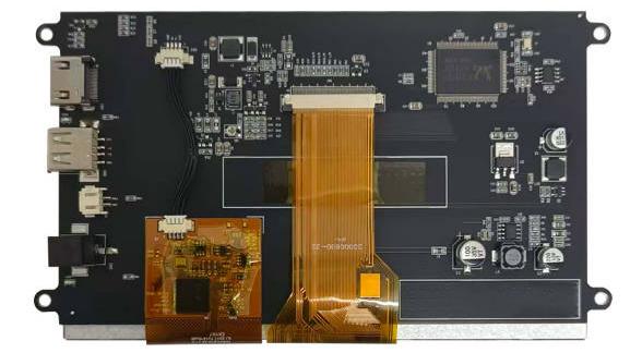
USB can carry touch coordinates, control commands, service data, or bridged display data when the hardware and software support those functions. Touch customization records may specify USB or IIC for the CTP while the LCD keeps a separate LVDS, RGB, or HDMI path. The user experience depends on the complete chain: sensor, touch controller, firmware, host driver, cable, and application software.
For that reason, a USB interface should be selected together with the host operating system, connector location, cable length, ESD protection, and expected update rate. A familiar connector is useful only when the electrical and software responsibilities are documented.
How Should Buyers Compare USB, SPI, and I2C?
USB vs SPI: Which Path Fits Display Data and Touch?
The practical question in USB vs SPI is not which acronym sounds faster. SPI is often used as a direct, embedded display-control path in compact modules, with the host responsible for timing and driver behavior. USB is a higher-level peripheral link that can simplify host integration when a suitable controller and driver already exist. The best choice depends on pixel workload, refresh needs, processor resources, cable distance, boot sequence, and software ownership.
Verified compact LCD records show RGB+SPI or RGB+MCU+SPI combinations. Those records should not be rewritten as USB products simply because the host board also has a USB connector. Conversely, a module with USB touch may still need a separate LCD timing path. An OEM should draw the signal map before comparing cost or connector convenience.
I2C vs USB: What Changes for Touch Controllers?
The I2C vs USB decision is usually a touch-controller and host-integration decision, not a choice between two universal LCD video standards. I2C can provide a compact control path between a touch controller and a host, while USB can offer a familiar peripheral connection when the controller and driver support it. Debugging, address management, interrupt behavior, cable routing, and driver availability all affect the final result.
A USB interface for touch should therefore be reviewed with the controller part number, firmware responsibility, USB device class, voltage level, connector pinout, and ESD plan. If the host expects I2C but the selected touch board exposes USB, a bridge may be required; if the host already supports USB input, the opposite conversion may add unnecessary complexity.
What Should an OEM Check Before Choosing a USB Display Assembly?
When Is an I2C to USB Converter Needed?
An I2C to USB converter may be considered when a touch controller and host expose different buses. The converter is not a magic improvement: it adds another device, power condition, firmware layer, and potential latency or compatibility point. Before adding one, the engineering team should confirm voltage levels, pull-ups, interrupt handling, USB enumeration, driver support, reset timing, cable shielding, and fault recovery.
The converter decision should also account for production control. A prototype may work with a development board while the final enclosure changes cable length, grounding, or EMI behavior. A stable production design needs a defined schematic, revision-controlled firmware, test procedure, and a clear owner for the bridge device.
Which USB LCD Panel Details Belong in the Validation Plan?
For a USB LCD panel, the validation plan should record the LCD resolution, luminance target, viewing direction, touch points, cover-glass thickness, bonding method, connector, FPC direction, cable length, operating temperature, power limits, and host software. The test should verify touch response at the edges, through the intended cover, under the intended gloves or stylus, and after the planned cleaning or vibration exposure.
The plan should also distinguish image tests from touch tests. A module may show a stable image through HDMI or LVDS while the USB touch path fails enumeration. It may also enumerate correctly while EMI, cable retention, or enclosure pressure causes intermittent coordinates. Sample acceptance should include the actual host, cable route, enclosure, brightness setting, and software build.
How Can CDTech Support a USB Display Connectivity Project?
Which Verified CDTech Module Can Anchor a USB Interface Review?
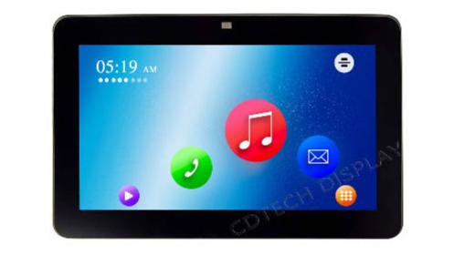
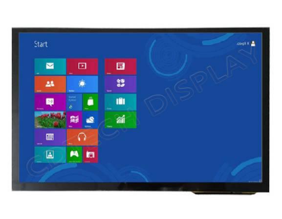
We can use the documented S070BWS59HD-DC35 as a practical reference for a USB touch/display review. The record identifies a 7.0-inch IPS display with 1024×600 resolution, HDMI for the LCD path, USB for the capacitive touch panel, 400-nit luminance, and an operating range of -20°C to +70°C.
The module is useful because it makes the separation between image and touch paths visible. An OEM can test the HDMI image chain, USB touch enumeration, controller behavior, cover-glass interaction, cable routing, and environmental conditions as one system. A second verified record, S101HWX34ED-DC29, shows another model-specific pattern: LVDS for the LCD and USB for the capacitive touch path.
What Should an OEM Include in a CDTech USB Enquiry?
With our products, an enquiry should include the host platform, operating system, image interface, USB touch requirement, target size, active area, outline drawing, connector and FPC direction, cable length, cover-glass thickness, bonding preference, luminance target, touch method, temperature range, EMI or ESD conditions, and sample-test method. These details let us separate a standard module from a configuration that needs custom FPC, connector, cover lens, backlight, or touch-controller work.
We can review the signal map and acceptance plan before a buyer commits to a production layout. Our products remain subject to model-level drawings, samples, and project validation; the USB interface should be approved together with the LCD path, mechanical package, software, and environmental test conditions.
FAQ
Q: Is USB better than SPI for every LCD?
A: No. USB may simplify a host peripheral connection, while SPI may suit a compact embedded display-control path. Compare the host processor, pixel workload, cable, driver, timing, power, and software before deciding between USB vs SPI.
Q: Do I need an I2C to USB converter for a touch panel?
A: Only when the touch controller and host expose different buses and the converter’s voltage, firmware, enumeration, latency, and EMC behavior are acceptable. Confirm the complete signal map before adding an I2C to USB converter.
Q: Can an LCD use USB for touch while using LVDS for the image?
A: Yes, that combination appears in verified model records, including an LVDS LCD path with USB capacitive touch. The exact controller, connector, cable, driver, and temperature range remain model-specific, so validate the complete USB LCD panel assembly.